
STEP — AP214 Cube Corner Points
A minimal, well-formed STEP AP214 file holding the eight corner points of a 10 mm cube. For testing STEP header and entity parsing and CAD-exchange tooling.
ISO-10303-21;
HEADER;
FILE_DESCRIPTION(('Novus Examples 10mm cube - corner points'),'2;1');
FILE_NAME('cube.step','2026-01-01T00:00:00',('Novus Examples'),(''),'Novus Examples','Novus Examples','');
FILE_SCHEMA(('AUTOMOTIVE_DESIGN { 1 0 10303 214 1 1 1 1 }'));
ENDSEC;
DATA;
#1=CARTESIAN_POINT('corner1',(0.0,0.0,0.0));
#2=CARTESIAN_POINT('corner2',(10.0,0.0,0.0));
#3=CARTESIAN_POINT('corner3',(10.0,10.0,0.0));
#4=CARTESIAN_POINT('corner4',(0.0,10.0,0.0));
#5=CARTESIAN_POINT('corner5',(0.0,0.0,10.0));
#6=CARTESIAN_POINT('corner6',(10.0,0.0,10.0));
#7=CARTESIAN_POINT('corner7',(10.0,10.0,10.0));
#8=CARTESIAN_POINT('corner8',(0.0,10.0,10.0));
ENDSEC;
END-ISO-10303-21;
Specifications
- Format
- STEP AP214 (ISO 10303-21)
- Entities
- 8 CARTESIAN_POINT (cube corners)
- Units
- mm
- Note
- minimal, well-formed
What is a .step file?
STEP (Standard for the Exchange of Product model data) is an ISO 10303 CAD format that stores precise boundary-representation solid geometry and product data as structured text. Unlike mesh formats, it preserves exact curves and surfaces for engineering use. It is the leading neutral format for mechanical CAD interchange.
How to use this file
Use an example STEP file to test CAD B-rep parsing, precise-geometry import, and interoperability tooling between mechanical design and CAM applications.
How to use this file for testing
“STEP — AP214 Cube Corner Points” is a deterministic Novus Examples fixture for Conversion testing. The same content exported across many formats and linked as a group, so you can convert one and diff against the expected twin.
Documented properties for this file: STEP AP214 (ISO 10303-21). Compare results against paired or grouped companions on this page when present (clean↔damaged, searchable↔scanned, or format twins) so scores stay reproducible across runs.
Download the file once, keep the path stable in CI or local scripts, and treat the spec table as the contract: dimensions, seeds, field lists, and roles are intentional. Corrupt or invalid samples are labelled as such — expect parsers to fail loudly rather than silently accept them.
3D and CAD fixtures carry one small, documented solid or scene. Convert and inspect against the known geometry, units, and structure; format twins let you diff interchange fidelity, and the 3D viewer previews the actual mesh.
Related files
- dxfDXF — CAD Cube (line geometry)A 10 mm cube drawn as 12 DXF LINE entities — the AutoCAD interchange format, written with ezdxf. For testing DXF parsers and CAD conversion.

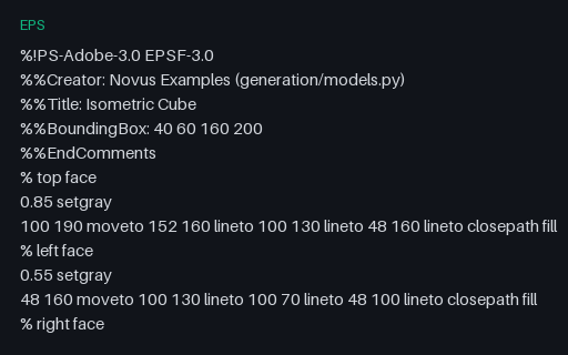
- epsEPS — Isometric Cube IllustrationAn isometric cube as Encapsulated PostScript — a 2D vector illustration with three shaded faces. For testing EPS/PostScript rendering and vector conversion.
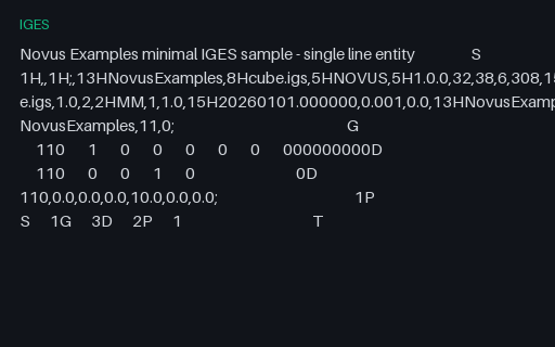
- igesIGES — Minimal Line EntityA minimal, well-formed IGES 5.3 file with a single LINE entity and correct Start/Global/Directory/Parameter/Terminate sections. For testing IGES parsers and CAD conversion.
- dxfSpur Gear — 16 teeth (DXF)A 16-tooth spur-gear profile as a closed DXF polyline with a central hub bore — real parametric CAD geometry (not a primitive). For testing DXF parsers, CAM tools, and CAD conversion.

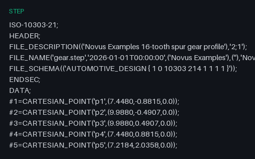
- stepSpur Gear — 16 teeth (STEP)The same 16-tooth spur-gear profile as STEP AP214 CARTESIAN_POINT entities — the CAD-exchange twin of the DXF, for testing STEP parsing.
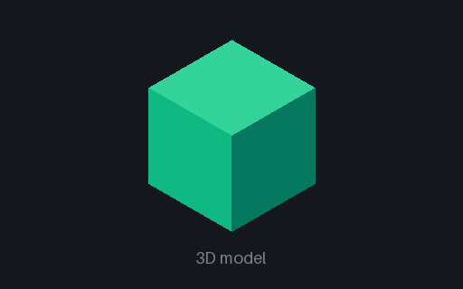
- 3mf3MF — Manufacturing CubeA 10 mm cube as 3MF — the modern OPC-packaged manufacturing format (a ZIP of model XML plus relationships). For testing 3MF readers and slicers.
Generated by generation/models.py. Free for any use, no attribution required — license.